【实验环境】
C3640-IK9O3S-M Version 12.4(10) + NM-16ESW模块
【实验目的】
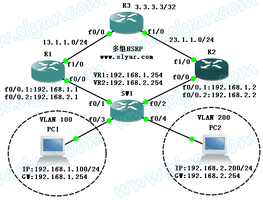
通过多组的HSRP实现网关的自动切换和负载分担。正常情况下R1作为VLAN 100的网关,R2作为VLAN 200的网关,以此作为负载分担,当上行链路或者下行链路Down掉之后,自动切换到备份网关,如果之前的链路恢复,则自动恢复原网关。
【实验拓扑】

【实验描述】
1、SW1使用3640+NM-16ESW模块模拟交换机,关闭路由功能,只作为2层交换机使用,将f0/3和f0/4分别加入VLAN 100和VLAN 200,f0/1和f0/2配置为trunk端口
2、PC1使用虚拟网关192.168.1.254,PC2使用虚拟网关192.168.2.254
3、为了保证VLAN间通信,在R1和R2上使用单臂路由技术
4、为了保证实验结果不会因为IGP影响,因此在R1和R2上使用NAPT技术将私有IP地址转换为公网IP地址,所有路由器上均不配置IGP。在R1和R2上配置默认路由即可
5、在R1和R2上配置HSRP热备份协议
【实验步骤】
1、使用VPCS配置PC1和PC2
PC1: ip 192.168.1.100/24 192.168.1.254
PC2: ip 192.168.2.200/24 192.168.2.254
2、配置SW1
使用GNS3创建VLAN时需要在VLAN database模式下,记得最后要"exit"应用配置
SW1#vlan database
SW1(vlan)#vlan 100
VLAN 500 added:
Name: VLAN0100
SW1(vlan)#vlan 200
VLAN 600 added:
Name: VLAN0200
SW1(vlan)#exit
APPLY completed.
Exiting....
SW1#
将端口划入相应VLAN
!
interface FastEthernet0/1
switchport mode trunk
!
interface FastEthernet0/2
switchport mode trunk
!
interface FastEthernet0/3
switchport access vlan 100
!
interface FastEthernet0/4
switchport access vlan 200
!
3、配置R3
!
interface Loopback0
ip address 3.3.3.3 255.255.255.255
!
interface FastEthernet0/0
ip address 13.1.1.3 255.255.255.0
!
interface FastEthernet1/0
ip address 23.1.1.3 255.255.255.0
!
4、配置R1的端口、单臂路由
R1(config)#interface FastEthernet0/0
R1(config-if)#no shutdown
R1(config-if)#interface FastEthernet0/0.1
R1(config-if)#encapsulation dot1Q 100
R1(config-if)#ip address 192.168.1.1 255.255.255.0
R1(config-if)#interface FastEthernet0/0.2
R1(config-if)#encapsulation dot1Q 200
R1(config-if)#ip address 192.168.2.1 255.255.255.0
R1(config-if)#interface FastEthernet1/0
R1(config-if)#ip address 13.1.1.1 255.255.255.0
R1(config-if)#no shutdown
5、配置R2的端口、单臂路由
R2(config)#interface FastEthernet0/0
R2(config-if)#no shutdown
R2(config-if)#interface FastEthernet0/0.1
R2(config-if)#encapsulation dot1Q 100
R2(config-if)#ip address 192.168.1.2 255.255.255.0
R2(config-if)#interface FastEthernet0/0.2
R2(config-if)#encapsulation dot1Q 200
R2(config-if)#ip address 192.168.2.2 255.255.255.0
R2(config-if)#interface FastEthernet1/0
R2(config-if)#ip address 23.1.1.2 255.255.255.0
R2(config-if)#no shutdown
6、在R1上配置NAPT和默认路由
R1(config)#access-list 11 permit 192.168.1.0 0.0.0.255
R1(config)#access-list 11 permit 192.168.2.0 0.0.0.255
R1(config)#ip nat inside source list 11 interface FastEthernet1/0 overload
R1(config)#interface FastEthernet0/0.1
R1(config-if)#ip nat inside
R1(config-if)#interface FastEthernet0/0.2
R1(config-if)#ip nat inside
R1(config-if)#interface FastEthernet1/0
R1(config-if)#ip nat outside
R1(config-if)#exit
R1(config)#ip route 0.0.0.0 0.0.0.0 13.1.1.3
7、在R2上配置NAPT和默认路由
R2(config)#access-list 22 permit 192.168.1.0 0.0.0.255
R2(config)#access-list 22 permit 192.168.2.0 0.0.0.255
R2(config)#ip nat inside source list 22 interface FastEthernet1/0 overload
R2(config)#interface FastEthernet0/0.1
R2(config-if)#ip nat inside
R2(config-if)#interface FastEthernet0/0.2
R2(config-if)#ip nat inside
R2(config-if)#interface FastEthernet1/0
R2(config-if)#ip nat outside
R2(config-if)#exit
R2(config)#ip route 0.0.0.0 0.0.0.0 23.1.1.3
8、在R1上配置HSRP,使得VLAN 100优先走R1
R1(config)#interface FastEthernet0/0.1
R1(config-if)#standby 1 ip 192.168.1.254 //配置组1,虚拟网关192.168.1.254
R1(config-if)#standby 1 priority 105 //将优先级从默认的100提高到105
R1(config-if)#standby 1 preempt //配置抢占模式
R1(config-if)#standby 1 track FastEthernet1/0 //配置上行链路跟踪,一旦down掉默认将优先级降低10,后面可跟数字自定义
R1(config-if)#interface FastEthernet0/0.2
R1(config-if)#standby 2 ip 192.168.2.254 //配置组2,虚拟网关192.168.2.254
R1(config-if)#standby 2 preempt //配置抢占模式
//组2没有配置优先级和跟踪,因为组2只是作为备份,默认优先级为100,就算上行链路不down,也比R2上的组2优先级低,因此也不需要track
9、在R2上配置HSRP,使得VLAN 200优先走R2
R2(config)#interface FastEthernet0/0.1
R2(config-if)#standby 1 ip 192.168.1.254
R2(config-if)#standby 1 preempt
R2(config-if)#interface FastEthernet0/0.2
R2(config-if)#standby priority 105
R2(config-if)#standby 2 ip 192.168.2.254
R2(config-if)#standby 2 priority 105
R2(config-if)#standby 2 preempt
R2(config-if)#standby 2 track FastEthernet1/0
//道理同R1,不解释了。组1在R1上优先级高,组2在R2上优先级高,只要他们各自的链路是up的,就一定可以保证是Active
10、在R1上查看HSRP,发现组1为Active,组2为Standby,正确
R1#sh standby brief
Interface Grp Prio P State Active Standby Virtual IP
Fa0/0.1 1 105 P Active local 192.168.1.2 192.168.1.254
Fa0/0.2 2 100 P Standby 192.168.2.2 local 192.168.2.254
11、在R2上查看HSRP,发现组1为Standby,组2为Active,正确
R2#sh standby brief
Interface Grp Prio P State Active Standby Virtual IP
Fa0/0.1 1 100 P Standby 192.168.1.1 local 192.168.1.254
Fa0/0.2 2 105 P Active local 192.168.2.1 192.168.2.254
12、在PC1上验证链路没有down时的tracert
VPCS[1]> tracert 3.3.3.3
1 192.168.1.1 20.000 ms 11.000 ms 11.000 ms
2 *13.1.1.3 77.000 ms (ICMP type:3, code:3, Destination port unreachable)
可以看到选择的是R1
13、在PC2上验证链路没有down时的tracert
VPCS[2]> tracert 3.3.3.3
1 192.168.2.2 29.000 ms 29.000 ms 9.000 ms
2 *23.1.1.3 84.000 ms (ICMP type:3, code:3, Destination port unreachable)
可以看到选择的是R2,这样就实现了负载分担
14、在PC1上观察当R1下行链路down掉时的热备份切换(这里down掉R1的f0/0.1接口)
结果不看了,持续ping一点停顿都没有,一个包都没掉,平滑过度到R2上了...
15、在PC1上观察当R1上行链路down掉时的热备份切换(这里down掉R1的f1/0接口)
VPCS[1]> ping 3.3.3.3 -t
3.3.3.3 icmp_seq=1 ttl=254 time=56.000 ms
3.3.3.3 icmp_seq=2 ttl=254 time=68.000 ms
3.3.3.3 icmp_seq=3 timeout //shutdown以后
3.3.3.3 icmp_seq=4 ttl=254 time=136.000 ms
3.3.3.3 icmp_seq=5 ttl=254 time=52.000 ms
3.3.3.3 icmp_seq=6 ttl=254 time=51.000 ms
3.3.3.3 icmp_seq=7 timeout //no shutdown以后
3.3.3.3 icmp_seq=8 ttl=254 time=59.000 ms
3.3.3.3 icmp_seq=9 ttl=254 time=50.000 ms
可以看到在down/up之间分别掉了1个包,效果非常好。热备份生效时R1和R2上的HSRP状态如下,R1的优先级降低了10,并且Standby了,R2都是Active了,当R1的链路恢复时,又会抢占回来。
R1#sh stan bri
Interface Grp Prio P State Active Standby Virtual IP
Fa0/0.1 1 95 P Standby 192.168.1.2 local 192.168.1.254
Fa0/0.2 2 100 P Standby 192.168.2.2 local 192.168.2.254
R2#sh stan bri
Interface Grp Prio P State Active Standby Virtual IP
Fa0/0.1 1 100 P Active local unknown 192.168.1.254
Fa0/0.2 2 105 P Active local 192.168.2.1 192.168.2.254
到这里实验就完成了。

下一篇 网络营销到底能带来什么样的价值